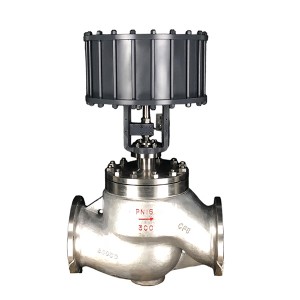
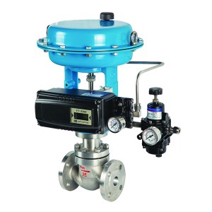
fluorine Lined pneumatic control valve
fluorine Lined pneumatic control valve
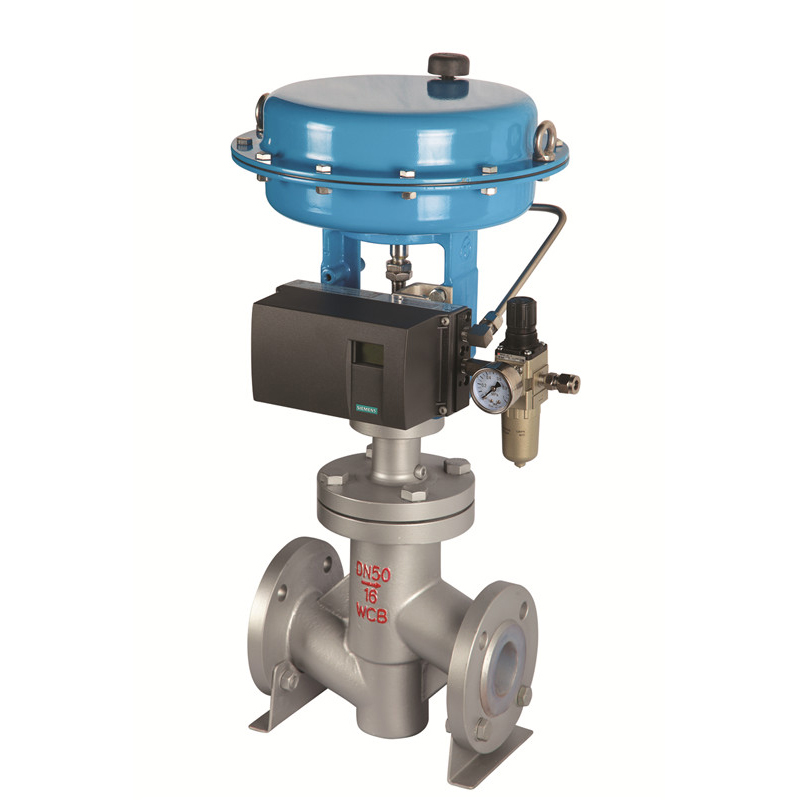
Pneumatic fluorine PTFE PFA lined control valve Features as below
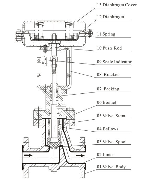
1. Good corrosion resistance: the inner cavity of Pneumatic fluorine lined control valve body, core, seat are lined with 3mm thick fluorine (PTFE,PEP,PRA) , which can withstand strong corrosive fluid.
2. Good sealing performance: double sealing with PTFE bellows and packing.
3. The leakage quantity is little, because the Pneumatic fluorine lined control valve core and seat are soft seal, leakage was far below the national Ⅳ level standard.
4. High adjustment accuracy: Pneumatic fluorine lined control valve adopts precise and small pneumatic and electric actuators, small in size and light in weight.
Pneumatic fluorine control valve technical parameter
| DNmm | G3/4 | 20 | 25 | 32 | 40 | 50 | 65 | 80 | 100 | 125 | 150 | 200 | |||||||
| valve seat dia mm | 3 | 4 | 5 | 6 | 7 | 8 | 10 | 15 | 20 | 26 | 32 | 40 | 50 | 65 | 80 | 100 | 125 | 150 | 200 |
| Rated flow coefficient Kv | 0.08 | 0.12 | 0.2 | 0.32 | 0.5 | 0.8 | 1.2 | 3.2 | 5 | 8 | 12 | 20 | 32 | 50 | 80 | 120 | 200 | 280 | 450 |
| PN Mpa | 1.0 1.6 | ||||||||||||||||||
| Flow characteristic | Straight line | Straight line;Percentages | |||||||||||||||||
| effective area cm2 | 280 | 400 | 600 | 1000 | |||||||||||||||
| stroke mm | 10 | 16 | 25 | 40 | 60 | ||||||||||||||
| spring range KP | 20~100,40~200,80~240 ;Segment:20~60,60~100 | ||||||||||||||||||
| Adjustable ratio | R=30:1 | ||||||||||||||||||
| temperature ºC | -20~+150 | ||||||||||||||||||
| % Basic error | Positioning | ±2.0 | No positioning | ±10 | |||||||||||||||
| %Return difference | ±1.5 | ±8 | |||||||||||||||||
| %Dead zone | ±1.5 | ±6 | |||||||||||||||||
| %Beginning and end deviation | ±2.0 | ±10 | |||||||||||||||||
| %Rated stroke deviation | ±2.5 | ||||||||||||||||||
| L/h Allowable leakage | 10-5×Rated capacity of the valve | ||||||||||||||||||
|
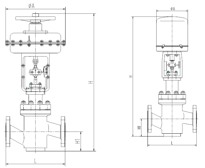
Nominal diameter DN |
15 |
20 |
25 |
32 |
40 |
50 |
65 |
80 |
100 |
150 |
|
L |
150 |
150 |
160 |
180 |
200 |
230 |
290 |
310 |
350 |
480 |
|
ΦA(Pneumatic) |
232 |
310 |
398 |
498 |
||||||
|
ΦA(Motorized) |
225 |
270 |
310 |
|||||||
|
H(Pneumatic) |
401 |
445 |
485 |
495 |
532 |
532 |
697 |
699 |
699 |
817 |
|
H(Motorized) |
540 |
675 |
695 |
720 |
880 |
890 |
945 |
|||
|
H1 |
50 |
65 |
70 |
80 |
71 |
88 |
102 |
140 |
170 |
190 |
|
Weight(Kg) |
17 |
17 |
19 |
21 |
28 |
35 |
54 |
70 |
85 |
150 |
Pneumatic fluorine control valve product structure
Size and weight
